Why do you need an electronic ignition
An electronic ignition will help your tired old flat four engine to start easier and run smoother, particularly at very high and very low RPM. The increased efficiency from using the electronic ignition can help lower your fuel consumption and reduce pollution emissions.
There are two main types of electronic ignition currently available, the first being that which completely replaces the 'electromechanical' ignition (contact breaker points, condenser, etc.) and the type that can be fitted as an 'up-grade', producing what is commonly called 'transistor assisted ignition'.
The Velleman kit is a 'transistor assisted ignition' and makes use of the 'conventional' mechanical timing switch (the points). The module will produce faster switching speeds, and reduce arcing across the point contacts. This equates to much less wear and tear on the points, less wasted ignition energy, and more power delivered to the spark plugs where it's needed.
The reason you are probably considering this kit is that it will save you in servicing costs. After installing this kit you should only have to replace the points every 50,000 miles instead of every 5,000 miles. That's a pretty big saving over the course of a few years when you consider that a set of points, etc will cost you at least £10 every 5,000 miles or so. The kit costs around £13 delivered plus a couple of quid for a box to put it in.
In a nutshell it's;
- Easy to fit, only four wires
- Transistor assisted ignition
- Significantly reduces contact breaker wear
- Original connections can be easily restored at any time
- Improved coil performance returns easier starting and cleaner combustion
What you need
- Soldering Iron
- Solder (flux type for soldering electrical connections)
- Wire cutters
- Wire stripper (if you can't strip wire with your cutter)
- Velleman Electronic Ignition Kit (Maplins sell them but a quick Google will pull up a stack more)
- A box to put the circuit board in. (we used an old laptop power supply box)
- 4 different coloured wires (>1mm sq conductor area). The length of wire depends on where you intend to fit it but around 50cm should do the trick.
- Drill and a drill bit set.
- 4 or more banana clips for attaching the kit to your car
- Inline fuse holder and a 2A fuse
- Insulating tape
- rubber grommit big enough for the 4 wires to pass through but not so big they flop about
How to do it
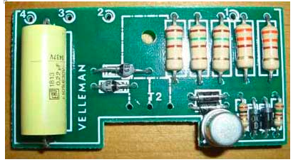
The instructions are pretty straight forward and clear enough even for an absolute novice. The circuit board is clearly labeled as are the individual components. The only thing to look out for are that the diodes are the right way around. They are keyed with the coloured end of the diode facing the double lined end of the diagram on the PCB. You can just see in the picture below the double lined diagram underneath the little white diodes next to the "VELLEMAN" marking. The black diodes have a silver end and the white ball like diodes have a black end.
- Easy to fit, only four wires
- Transistor assisted ignition
- Significantly reduces contact breaker wear
- Original connections can be easily restored at any time
- Improved coil performance returns easier starting and cleaner combustion
What you need
- Soldering Iron
- Solder (flux type for soldering electrical connections)
- Wire cutters
- Wire stripper (if you can't strip wire with your cutter)
- Velleman Electronic Ignition Kit (Maplins sell them but a quick Google will pull up a stack more)
- A box to put the circuit board in. (we used an old laptop power supply box)
- 4 different coloured wires (>1mm sq conductor area). The length of wire depends on where you intend to fit it but around 50cm should do the trick.
- Drill and a drill bit set.
- 4 or more banana clips for attaching the kit to your car
- Inline fuse holder and a 2A fuse
- Insulating tape
- rubber grommit big enough for the 4 wires to pass through but not so big they flop about
How to do it
The instructions are pretty straight forward and clear enough even for an absolute novice. The circuit board is clearly labeled as are the individual components. The only thing to look out for are that the diodes are the right way around. They are keyed with the coloured end of the diode facing the double lined end of the diagram on the PCB. You can just see in the picture below the double lined diagram underneath the little white diodes next to the "VELLEMAN" marking. The black diodes have a silver end and the white ball like diodes have a black end.
The art of soldering
Soldering isn't difficult just a little fiddly. The thing you have to remember is that the solder will flow to the hottest part. If you place the iron on the PCB so that the majority of the iron is touching the wire poking through, the solder should flow up from the PCB to the wire leaving a nice clean pyramid shaped join. Leave the legs of the components on until after you've soldered all the components on then trim them off with your wire cutters. This way if you find you make a mistake it's easy to remove the component and fix the problem
Fitting it into your box
This is where your ingenuity need to come to the fore. Everybody's box will probably be slightly different so describing this is next to impossible but I can give you a couple of hints.
1. The heat sink needs to go outside your box.
2. If you find the transistor legs aren't long enough because the big resistor (well I think it's a resistor) is in the way then why not mount the resistor on the other side of the board? You can do this with any of the components except maybe the transistor. Just make sure you check the direction of the diodes.
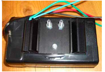
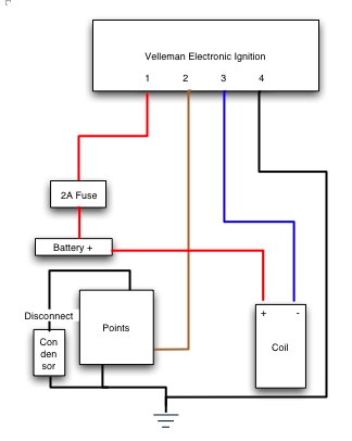
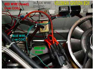
Connecting it up to the car
The diagrams below shows how the kit connects up to the car. Note that in the photo the green wire is the same as the brown wire in the diagram. The photo is of the kit installed in one of the club members Splitty.
The diagrams below shows how the kit connects up to the car. Note that in the photo the green wire is the same as the brown wire in the diagram. The photo is of the kit installed in one of the club members Splitty.